Car Hydraulics: Specs, Systems, and Safe, High-Performance Setups
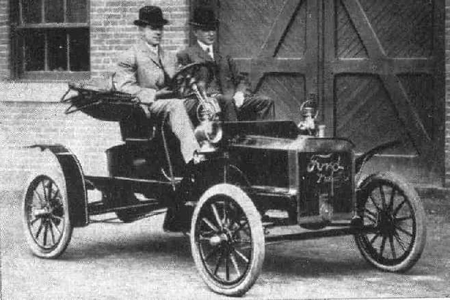
Lowrider hydraulic systems represent one of the most technically demanding forms of automotive customization. What began in 1950s Los Angeles as a creative response to anti-cruising laws has evolved into a sophisticated engineering discipline combining mobile hydraulics, high-current electrical systems, and structural reinforcement.
Yet despite the cultural prominence of hydraulic lowriders, precise technical specifications have remained scattered across forums, shop manuals, and tribal knowledge. This guide consolidates the engineering parameters that define safe, high-performance hydraulic installations.
Operating Pressure: The Foundation of Hydraulic Performance
Hydraulic systems work by transmitting force through incompressible fluid. The operating pressure directly determines how much force your cylinders can generate — and how quickly your car responds to switch commands.
Typical Pressure Ranges
Most lowrider hydraulic systems operate in the 1,200–3,000 psi (8.3–20.7 MPa) range:
- • Street cruiser setups: 1,200–1,800 psi — adequate for smooth lifts and daily driving
- • Show/competition setups: 2,000–2,500 psi — faster response, higher hops
- • Extreme hopping rigs: 2,500–3,000+ psi — maximum performance, requires reinforced components
For context, industrial hydraulic equipment from manufacturers like Bosch Rexroth rates radial piston pumps up to 700 bar (10,150 psi), demonstrating that lowrider pressures fall well within proven engineering parameters when proper components are used.
Pumps and Motors: The Heart of the System
Electric gear pumps are the standard for lowrider applications, chosen for their compact size, rapid response, and compatibility with DC power systems.
Pump Specifications
- • Flow Rate: 1–4 GPM (3.8–15.1 L/min) — higher flow means faster lift speed
- • Motor Power: 1–3 HP (0.75–2.2 kW) equivalent DC motor rating
- • Current Draw: 150–400 A under load per pump at 12V DC
- • Pump Type: Gear pump (most common), some use vane pumps for quieter operation
Most competition setups run two pumps minimum — one for front, one for rear — allowing independent control and balanced power distribution. Four-pump setups (one per corner) provide maximum flexibility for three-wheel motion and complex hop sequences.
Cylinders and Rams: Force Delivery
Hydraulic cylinders convert fluid pressure into mechanical force. The bore diameter and stroke length determine both the lifting force and travel range.
Cylinder Specifications
- • Bore Diameter: 2–4 in (50–100 mm) — larger bore means more force
- • Stroke Length: 4–8 in (100–200 mm) — determines max travel
- • Rod Diameter: 1–2 in (25–50 mm) — must handle side loads
Force Calculations
The force generated by a hydraulic cylinder follows a simple formula:
Force (lbf) = Pressure (psi) × Piston Area (in²)
- • 3-inch bore at 2,000 psi: 2,000 × 7.07 = 14,140 lbf (62.9 kN)
- • 4-inch bore at 2,500 psi: 2,500 × 12.57 = 31,425 lbf (139.8 kN)
These forces explain why frame reinforcement is critical — stock unibody mounting points were never designed for loads of this magnitude.
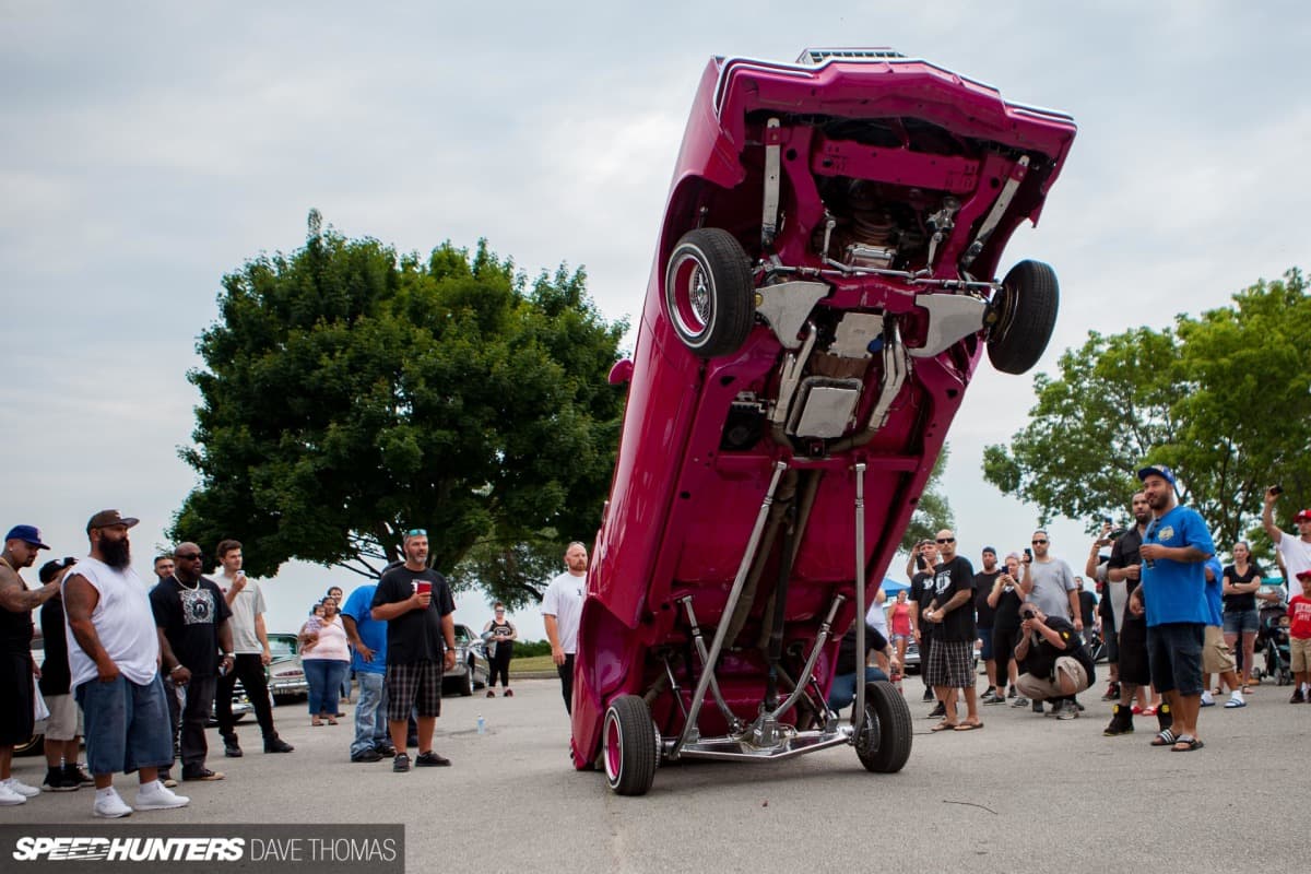
Travel and Hop Height: What's Achievable
Vertical travel depends on cylinder stroke, mounting geometry, and suspension design:
- • Street setups: 3–8 inches (75–200 mm) corner travel
- • Show/hop setups: 8–14 inches (200–360 mm)
- • Extreme competition: 12–24+ inches (300–600+ mm) momentary hop height
The distinction between static travel (sustained position) and dynamic hop height (momentary peak during hopping) is important. Hop heights exceeding 40–50 inches are achieved through rapid pressure cycling that launches the vehicle, not sustained cylinder extension.
Accumulators: Smoother Operation
Accumulators store pressurized fluid and gas, providing several benefits:
- • Dampening pressure spikes during rapid cycling
- • Smoother ride quality at cruising height
- • Reserve pressure for consistent performance
Accumulator Specifications
- • Type: Bladder or piston
- • Precharge Pressure: 100–300 psi (0.7–2.1 MPa)
- • Volume: 0.5–5 L (0.13–1.3 gal)
Precharge pressure should be set to approximately 30–40% of minimum system operating pressure for optimal performance.
Hydraulic Fluid: Choosing the Right Oil
Fluid selection affects system longevity, seal compatibility, and temperature performance:
- • Recommended: Anti-wear hydraulic oil, ISO VG 32–46
- • Alternative: Automatic transmission fluid (ATF) — compatible with many seal materials
- • Avoid: Brake fluid (attacks seals), motor oil (inadequate anti-wear additives)
ISO VG 32 is preferred for colder climates; ISO VG 46 provides better protection in hot weather or high-duty-cycle competition use.
Hoses and Fittings: The Pressure Network
Hydraulic hoses must withstand repeated pressure cycling without failure. Industry standards provide clear guidance:
Hose Specifications
- • Inside Diameter: 3/8–3/4 in (9.5–19 mm)
- • Fitting Standard: AN/JIC or SAE
- • Working Pressure: Match or exceed system pressure
- • Burst Rating: ≥4× working pressure (standard safety factor)
Critical: Always use hydraulic-rated hoses — never substitute air hose, fuel line, or other non-rated materials. A hose failure at 2,000+ psi can cause serious injury.
Electrical System: Powering the Pumps
The electrical demands of hydraulic pumps require careful system design. A single pump drawing 300A at 12V represents 3,600 watts — equivalent to running three household space heaters simultaneously.
Battery Configuration
- • Basic street: 4× 12V batteries, 50–80 Ah total — adequate for occasional use
- • Show/moderate: 6× 12V batteries, 80–150 Ah total — supports extended operation
- • Competition: 8–10× 12V batteries, 150–200+ Ah total — required for heavy hopping
Deep-cycle or AGM batteries are preferred over standard automotive batteries due to better tolerance for repeated deep discharge cycles.
Wiring Requirements
- • Main feeds: 1/0 to 4 AWG (53–21 mm²)
- • Solenoid circuits: 8–12 AWG
- • All circuits: Properly fused at battery and distribution points
Undersized wiring causes voltage drop, reducing pump performance and creating fire hazards from overheated conductors.
For detailed wiring diagrams and community-tested configurations, the LayItLow.com forums remain an invaluable technical resource.
Safety Systems and Settings
Hydraulic systems store enormous energy. Proper safety measures protect both the vehicle and operator:
Relief Valve Settings
Relief valves prevent over-pressurization by venting excess fluid back to the reservoir:
- • Set relief valves 10–15% above normal operating pressure
- • Example: 2,000 psi system → relief valve at 2,200–2,300 psi
- • Never disable or bypass relief valves
Maintenance Schedule
- • Monthly: Visual inspection of hoses, fittings, mounts
- • Every 6 months: Check fluid level, inspect for leaks
- • Annually: Fluid change, filter replacement
- • Every 500–1,000 hours: Complete system service
Frame Reinforcement: Structural Integrity
Stock vehicle frames and unibodies were not designed for hydraulic loads. Proper reinforcement is non-negotiable:
- • Cylinder mounts: Boxed crossmembers with gussets and backing plates
- • A-arm mounts: Reinforced or replaced with tubular units
- • Fasteners: Grade 8 or higher, torqued to specification
- • Welds: Full-penetration welds by qualified fabricators
Cutting corners on frame reinforcement leads to cracked welds, torn mounting points, and potentially catastrophic structural failure during hopping.
Visualizing Your Hydraulic Build
Before committing to a hydraulic installation, visualizing the overall aesthetic helps ensure your stance, paint, and wheel choices work together. Modern car customization platforms like CarCustomizer.io allow you to preview your lowrider's look at different ride heights — helping you dial in the perfect dropped stance before the first cylinder is mounted.
Conclusion: Engineering Meets Culture
Lowrider hydraulics sit at the intersection of mobile hydraulic engineering, high-current electrical systems, and automotive fabrication. The specifications outlined here — 1,200–3,000 psi operating pressures, 1–4 GPM pump flows, 2–4 inch cylinder bores, ISO VG 32–46 fluids, and properly rated hoses and wiring — represent proven parameters used across thousands of successful builds.
Understanding these technical foundations transforms hydraulic customization from guesswork into engineering. Whether you're building a boulevard cruiser or a competition hopper, respecting these specifications ensures your lowrider performs safely and reliably for years to come.